


Introduction
A cyber range is a platform that provides hands-on experience to cybersecurity professionals, creating different scenarios within a virtual environment and in some cases incorporates physical devices. That platform must be able to provision multiple virtual machines and interconnect them with physical devices, and with the trainee network, in a horizontally scalable design.
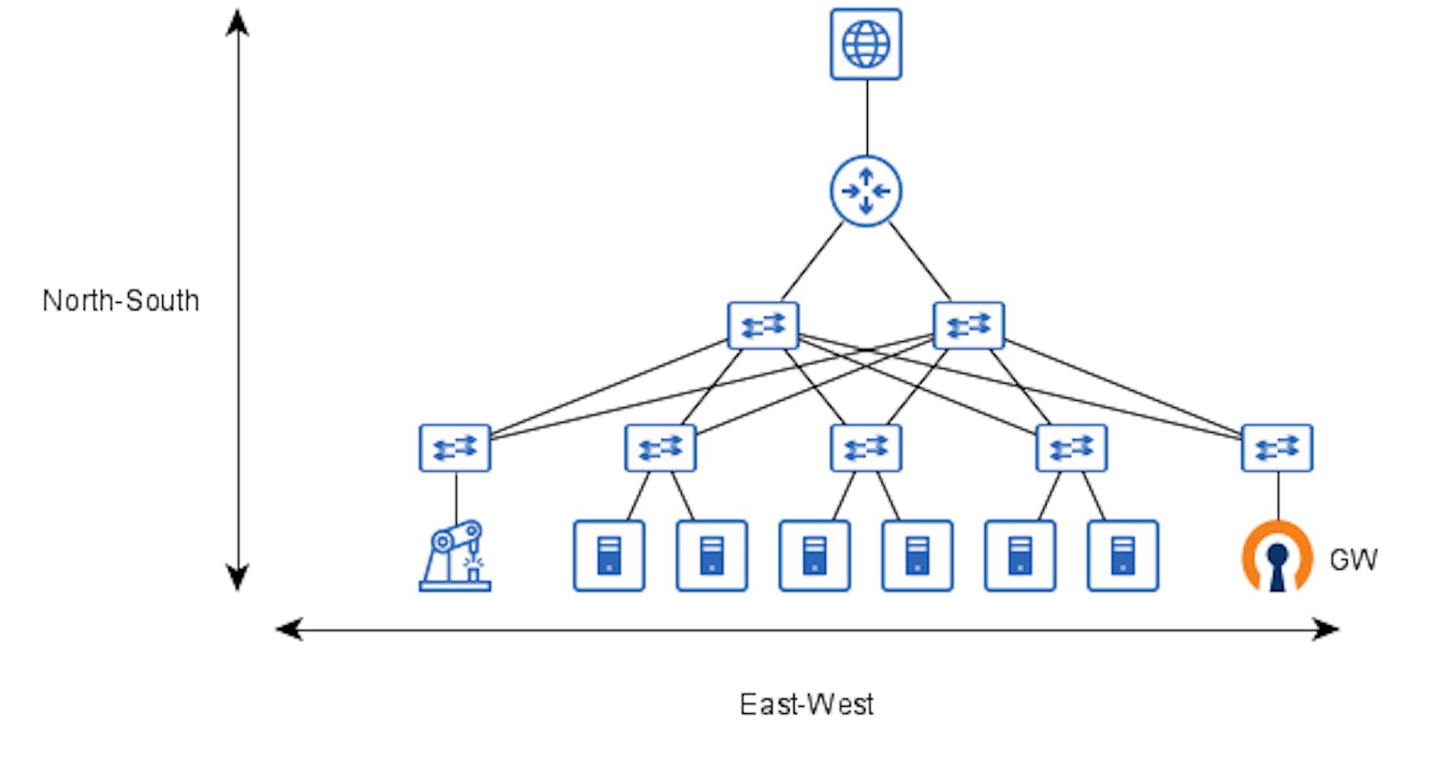
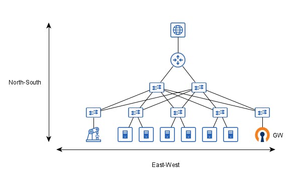
From a network perspective, the traffic in the cyber range could be divided into two different scopes the North-South traffic which represents the flow through the end-user and the application under test, and the East-West traffic which represents the traffic between the serves in the infrastructure.
Network Analysis
The network topology must provide logical separation from each different scenario and client, without allowing that the scenario traffic flows to the outside world and attack hosts that aren’t involved in the scenario.
For that, a VPN server, like OpenVPN, could be used as a gateway for the cyber range separating the external world from the lab environment and allowing logical segregation from each student or analyst using the lab.
Once connected to the VPN Server the client traffic must be separated from the other clients and forwarded to the desired scenario, for that the technology used in the East-West traffic has great relevance in the GW configuration, and for that will be presented first.
EAST-WEST Traffic
The traditional approach for data center interconnection, based on VLANs, requires that for each new network segment, represented by a VLAN, all the devices on the network topology be reconfigured by the addition of that VLAN on the VLAN database, and in some cases, the cyber range lab scenario could have more than one internal network.
When considering the addition of physical devices outside the data center, using VLANs could bring several limitations to the environment because the VLAN should be extended outside the data center to the environment where the equipment is, which adds an extra layer of complexity and depending on the legacy network topology the L2 link between the data center and the physical devices lab might no be possible.
Additionally to those limitations, the VLAN approach relies on some flavor of STP, and for that, there is a natural bandwidth loss, because of the blocking mechanism of STP.
Another approach is using VxLAN, which is an encapsulation protocol that provides L2 connectivity over an underlying L3 network, when comparing with the traditional VLAN approach the VXLAN allows to network to scale to 16 million different networks in contrast to 4094 that VLAN allows. Since the L2 Frames are encapsulated on UDP L3 packets the network fabric can use an L3 protocol like OSPF or IS-IS, allowing full use of the network capacity and reducing the configuration required to create a new network segment.
For the L2 connectivity each VXLAN Tunnel End Point (VTEP), must share its Mac Address table with all other VTEPs which can be done in two forms, using multicast packets, or by BGP EVPN. This implementation focus on the EVPN mode, where each server has an FRR router running a BGP instance, and for each new network the hypervisor creates it creates a bridge interface and attaches the interfaces of the virtual machine and a VXLAN interface.
NORTH-SOUTH TRAFFIC
This traffic represents the trainees' requests, that once connected to the VPN server must be separated from each other and forwarded to the desired scenario, the VPN server analyzed in this article is the OpenVPN, which has two interfaces configuration modes the TAP, and the TUN.
In the TAP mode, each process of the VPN server raises a TAP interface and connects all the clients on that L2 interface, and listen on different UDP port, since the TAP interfaces is an L2 interface the L3 addressing can be delegated to the scenario Firewall and the network topology would be something like the image bellow:
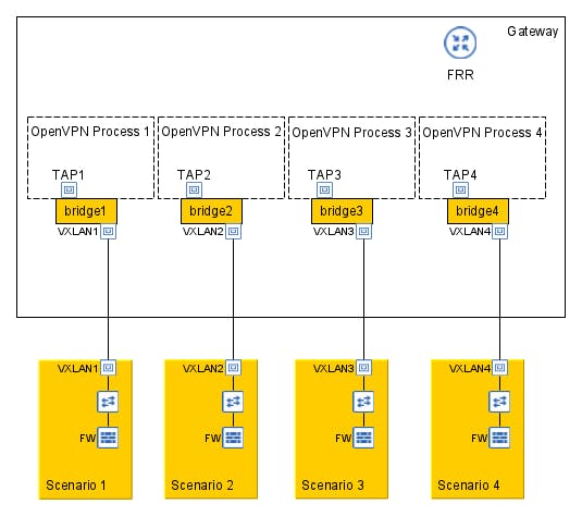
The topology presented in Figure 2 has a simpler implementation but with two main drawbacks, the first one is the greater administrative complexity since each scenario requires a new OpenVPN process with its configuration file, and management stack, the other drawback is that each OpenVPN process is bound to a TCP/UDP port what limit the scalability to the number of available ports.
In the TUN mode, the OpenVPN process raises a TUN interface and connects all clients to a single L3 interface, and for each client, the OpenVPN delivers a distinct /30 subnet that can be configured for each client fixing the client source IP.
The drawback of TUN interfaces is that they cannot be attached directly to the bridge, and requires a routing layer in the configuration, which will be described in detail below.
Gateway network architecture
The chosen mode for OpenVPN is the TUN, and in that mode, the main problem is network segregation, because each scenario may have the same network segment and all the trainees belong to the same network segment.
To deal with that we need to completely segregate the trainee network stack from each scenario and then separate their traffic, for the network segregation it’s possible to use a network namespace which is logically another copy of the network stack, with its routes, firewall rules, and network devices.
For the trainee traffic separation, OpenVPN gives control over the client source IP. Then with SDN protocol OpenFlow it’s possible to forward each trainee to a separate scenario, based on source IP.
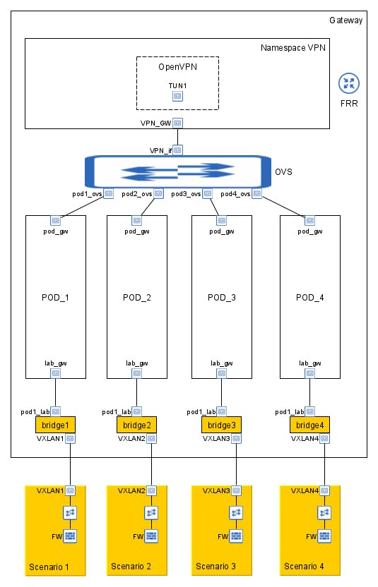
In the above diagram, "Namespace VPN" and the "POD_N" are network namespaces, a logical copy of the network stack from the host system. The network namespaces gives flexibility to the gateway design, by providing total separation between the different network scopes. Now with TUN implementation of OpenVPN, all clients receives an IP address inside the same network segment. And OpenVPN allows to configure which IP Address each client receives, information that gonna used for separate the traffic.
The next step challenge is to forward the traffic between the VPN and the POD namespaces. Since all labs has the same network prefix it isn't possible to the VPN namespace keep several equal prefixes in its routing table. And even if it was possible to keep all prefixes the routing processor would choose the best and forward all traffic to it, without separating the traffic.
With that problem in mind, it would be simpler if the VPN namespace doesn't deal with traffic separation, and uses only one route to forward the traffic to the labs. For that is necessary that the VPN namespace sees all the POD's namespaces as the same thing, that is possible by using the same IP and MAC address in each of the pod_gw interfaces, and setup static arp address resultion for the pod_gw IP.
By doing this no matter which POD namespace the traffic belongs to, the VPN namespace creates the same Ethernet packet and everyone receives and forwards it in the same way.
Now with the homogeneous traffic between the VPN and POD namespaces, it's time for the selection and separation. For that OpenFlow gives the required flexibility, by allowing forward traffic based on any field of the packet header, in this scenario the source IP.
That is possible using Open VirtualSwitch and adding flows dynamically on POD creation, the following is an sample flow:
# Traffic from VPN to POD
$> ovs-ofctl add-flow <ovs_name> ip,priority=33001,in_port=<vpn_if>,nw_src=<client_ip>,actions=output:<podx_ovs>
# Traffic from POD to VPN
$> ovs-ofctl add-flow <ovs_name> ip,priority=33001,in_port=<podx_ovs>,actions=output:<vpn_if>
The last step is connecting the POD to the lab scenarios, for that we need to bring the L2 connectivity of each POD back to the global space. For that connection we create one bridge interface for each lab scenario, and connect it to a VxLAN interface and a VETH pair one attached to the bridge and another on the POD namespace. That way all traffic forwarded to the POD namespace enters in its veth interface and is forwarded to other pair attached in the bridge.
When that traffic arrives in the bridge the VxLAN learns its MAC address and FRR with BGP-EVPN floods that information to the others servers. Finally to simplify the lab scenarios, its possible to implement a network firewall as gateway of the several hosts. Each host has the firewall as default gateway and the firewall forwards the traffic back to the clients using the VPN Gateway.