In this article, we’re going to map a network topology using Nornir, Genie, and NetworkX, investigate the Layer 2 topology consistency, and then, using the NetBox API, model the devices with their connections on NetBox.
This article has been divided into four parts: the first part presents the lab scenario and the network topology, the second shows how to use Nornir and Genie to gather data end parse, the third use NetworkX to create a graph and make some analysis, and finally, push all the data gathered to NetBox.
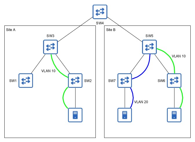
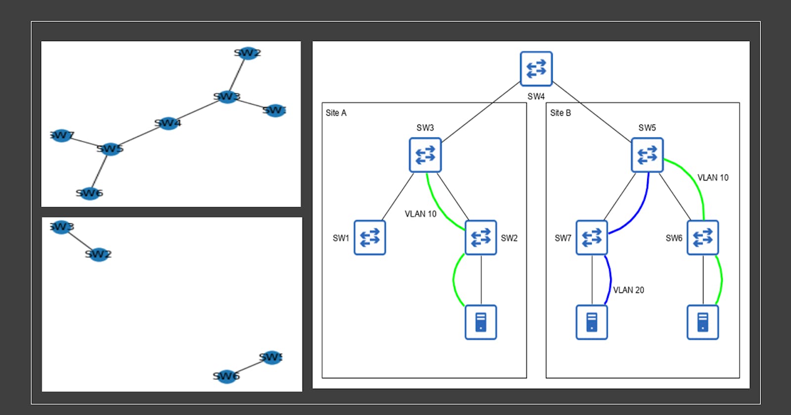
For this article, I’m going to use the Multi-IOS Cisco Test Network Lab of DevNet Sandbox, with the topology of the diagram below, where the blue lines represent VLAN 20 and the green ones the VLAN 10.
This kind of topology happens when you perform the integration of two sites and there’s a conflict in VLANs assignment, or in a poorly documented environment where staff doesn’t have control over the already utilized VLANs, or even when someone makes a configuration mistake, like forget to create a VLAN on some device.

Data Gathering
The first thing that should be done is mapping the network topology, for that, all the devices must have some link layer discovery protocol enabled, LLDP or CDP, and with the netmiko_send_command module to collect the connection state, as the code snippet below:
from nornir import InitNornir
from nornir_utils.plugins.functions import print_result
from nornir_netmiko.tasks import netmiko_send_command

nr = InitNornir()
getCDPNeighbors = nr.run(
    name="get CDP neighbors",
    task= netmiko_send_command,
    command_string = "show cdp neighbors detail"
)
print_result(getCDPNeighbors)
output
get CDP neighbors***************************************************************
* SW1 ** changed : False *******************************************************
vvvv get CDP neighbors ** changed : False vvvvvvvvvvvvvvvvvvvvvvvvvvvvvvvvvvvvvv INFO
-------------------------
Device ID: SW3.local
Entry address(es):
  IP address: 172.16.30.59
Platform: Cisco ,  Capabilities: Router Switch IGMP
Interface: GigabitEthernet0/1,  Port ID (outgoing port): GigabitEthernet0/2
Holdtime : 172 sec

Version :
Cisco IOS Software, vios_l2 Software (vios_l2-ADVENTERPRISEK9-M), Version 15.2(CML_NIGHTLY_20180619)FLO_DSGS7, EARLY DEPLOYMENT DEVELOPMENT BUILD, synced to  V152_6_0_81_E
Technical Support: http://www.cisco.com/techsupport
Copyright (c) 1986-2018 by Cisco Systems, Inc.
Compiled Tue 19-Jun-18 06:06 by mmen

advertisement version: 2
VTP Management Domain: ''
Native VLAN: 1
Duplex: full
Management address(es):
  IP address: 172.16.30.59


Total cdp entries displayed : 1
^^^^ END get CDP neighbors ^^^^^^^^^^^^^^^^^^^^^^^^^^^^^^^^^^^^^^^^^^^^^^^^^^^^^
* SW2 ** changed : False *******************************************************
But that code snippet returns unstructured data, just like the device output, which isn’t useful for processing, thus, it is required that the output be parsed.
For parsing the output there’re some options, which are, develop a parser from scratch, use genie oper_fill_tabular module, change the serializer from Nornir to Genie using the built-in parser, and use the use_genie parameter on netmiko as the snippet below:
from nornir import InitNornir
from nornir.core.task import Task, Result
from nornir_utils.plugins.functions import print_result


getNeighbors_obj = nr.run(
    name="get CDP neighbors",
    task= netmiko_send_command,
    command_string = "show cdp neighbors detail",
    use_genie = True
)
print_result(getNeighbors_obj)
output
get CDP neighbors***************************************************************
* SW1 ** changed : False *******************************************************
vvvv get CDP neighbors ** changed : False vvvvvvvvvvvvvvvvvvvvvvvvvvvvvvvvvvvvvv INFO
{ 'index': { 1: { 'advertisement_ver': 2,
                  'capabilities': 'Router Switch IGMP',
                  'device_id': 'SW3.local',
                  'duplex_mode': 'full',
                  'entry_addresses': {'172.16.30.59': {}},
                  'hold_time': 142,
                  'local_interface': 'GigabitEthernet0/1',
                  'management_addresses': {'172.16.30.59': {}},
                  'native_vlan': '1',
                  'platform': 'Cisco ',
                  'port_id': 'GigabitEthernet0/2',
                  'software_version': 'Cisco IOS Software, vios_l2 Software '
                                      '(vios_l2-ADVENTERPRISEK9-M), Version '
                                      '15.2(CML_NIGHTLY_20180619)FLO_DSGS7, '
                                      'EARLY DEPLOYMENT DEVELOPMENT BUILD, '
                                      'synced to  V152_6_0_81_E\n'
                                      'Technical Support: '
                                      'http://www.cisco.com/techsupport\n'
                                      'Copyright (c) 1986-2018 by Cisco '
                                      'Systems, Inc.\n'
                                      'Compiled Tue 19-Jun-18 06:06 by mmen',
                  'vtp_management_domain': ' '}},
  'total_entries_displayed': 1}
^^^^ END get CDP neighbors ^^^^^^^^^^^^^^^^^^^^^^^^^^^^^^^^^^^^^^^^^^^^^^^^^^^^^
But that approach has some problems, like Genie and PyATS aren’t thread-safe (pubhub.devnetcloud.com/media/pyats/docs/asy..) and some times some “mysterious” problems can occur (github.com/ktbyers/netmiko/issues/1347), or Genie's limited vendor support.
To solve those issues it’s possible to merge the netmiko_send_command, with the ShowCdpNeighborsDetail inside a new Task, what should solve the threading problem and allow multi-vendor support, giving the code below:
from nornir import InitNornir
from nornir.core.task import Task, Result
from nornir_utils.plugins.functions import print_result
from nornir_netmiko.connections import CONNECTION_NAME
from genie.libs.parser.iosxe.show_cdp import ShowCdpNeighborsDetail
from unittest.mock import Mock

def getCDPnei_obj(task: Task) -> Result:
    if(task.host.platform == 'ios'):
        net_connect = task.host.get_connection(CONNECTION_NAME, task.nornir.config)
        result = net_connect.send_command("show cdp neighbors detail")
        parser = ShowCdpNeighborsDetail(Mock())
        result = parser.cli(result)

    return Result(
        host= task.host,
        result= result
    )
getNeighbors_obj = nr.run(
    name="get CDP neighbors",
    task= getCDPnei_obj
)
print_result(getNeighbors_obj)
output
get CDP neighbors***************************************************************
* SW1 ** changed : False *******************************************************
vvvv get CDP neighbors ** changed : False vvvvvvvvvvvvvvvvvvvvvvvvvvvvvvvvvvvvvv INFO
{ 'index': { 1: { 'advertisement_ver': 2,
                  'capabilities': 'Router Switch IGMP',
                  'device_id': 'SW3.local',
                  'duplex_mode': 'full',
                  'entry_addresses': {'172.16.30.67': {}},
                  'hold_time': 141,
                  'local_interface': 'GigabitEthernet0/1',
                  'management_addresses': {'172.16.30.67': {}},
                  'native_vlan': '1',
                  'platform': 'Cisco ',
                  'port_id': 'GigabitEthernet0/2',
                  'software_version': 'Cisco IOS Software, vios_l2 Software '
                                      '(vios_l2-ADVENTERPRISEK9-M), Version '
                                      '15.2(CML_NIGHTLY_20180619)FLO_DSGS7, '
                                      'EARLY DEPLOYMENT DEVELOPMENT BUILD, '
                                      'synced to  V152_6_0_81_E\n'
                                      'Technical Support: '
                                      'http://www.cisco.com/techsupport\n'
                                      'Copyright (c) 1986-2018 by Cisco '
                                      'Systems, Inc.\n'
                                      'Compiled Tue 19-Jun-18 06:06 by mmen',
                  'vtp_management_domain': ' '}},
  'total_entries_displayed': 1}
^^^^ END get CDP neighbors ^^^^^^^^^^^^^^^^^^^^^^^^^^^^^^^^^^^^^^^^^^^^^^^^^^^^^
In the getCDPnei_obj implementation, first, it checks the device platform (in this article implemented only to Cisco IOS), then, using the netmiko_send_command, issues the command to the device, use a Mock object to simulates a Genie's Device and calls the correspondent Parser, this way, all the Genie's functions called are thread-safe because there aren’t any resource concurrence.
Finally, to gather data from the VLAN database, the only change is the command issued to the devices, giving the following code, and finishing this part of the article.
from nornir import InitNornir
from nornir.core.task import Task, Result
from nornir_utils.plugins.functions import print_result
from nornir_netmiko.connections import CONNECTION_NAME
from nornir_netmiko.tasks import netmiko_send_command
from genie.libs.parser.iosxe.show_cdp import ShowCdpNeighborsDetail
from genie.libs.parser.iosxe.show_vlan import ShowVlan
from unittest.mock import Mock


def getCDPnei_obj(task: Task) -> Result:
    if(task.host.platform == 'ios'):
        net_connect = task.host.get_connection(CONNECTION_NAME, task.nornir.config)
        result = net_connect.send_command("show cdp neighbors detail")
        parser = ShowCdpNeighborsDetail(Mock())
        result = parser.cli(result)

    return Result(
        host= task.host,
        result= result
    )


def getVlan_obj(task: Task) -> Result:
    if(task.host.platform == 'ios'):
        net_connect = task.host.get_connection(CONNECTION_NAME, task.nornir.config)
        result = net_connect.send_command("show vlan")
        parser = ShowVlan(Mock())
        result = parser.cli(result)
    return Result(
        host= task.host,
        result= result
    )

nr = InitNornir()

getNeighbors_obj = nr.run(
    name="get CDP neighbors",
    task= getCDPnei_obj
)

getVlan_obj = nr.run(
    name="get vlans",
    task= getVlan_obj
)
Graph Analysis
Now, with the data in getNeighbors_obj and getVlan_obj, which are an instance of AggregatedResult, to get the device's data you need to call it like that: Object[“hostname”][“results”], and the result object is the same as the output of the print_result module.
With that in mind let’s build our network with NetworkX, which is a Python Framework for graph analysis, to do that it's required to create a Graph object, that can be of the following types:
- Graph: Are graphs that hold undirected edges. Self loops are allowed but multiple (parallel) edges are not.
- DiGraph: Are graphs that hold directed edges. Self loops are allowed but multiple (parallel) edges are not.
- MultiGraph: Are graphs that hold undirected edges. Self loops and multiple (parallel) edges are allowed.
- MultiDiGraph: Are graphs that hold directed edges. Self loops and multiple (parallel) edges are allowed
For a network topology, the most appropriate kind of Graph is the MultiGraph because a Network Device can connect multiple times to another one and there isn’t any orientation on the edges. To create our graph, first, you need to instantiate the appropriate kind of graph and then add all the nodes, in our scenario the nodes are the network devices, which are accessible by the keys of the data objects:
import networkx as nx
nodes = list(getNeighbors_obj.keys())
G = nx.MultiGraph()
G.add_nodes_from(nodes)
With our Graph populated with nodes, let’s add some data to them, iterating over the G.nodes and accessing the getVlan_obj to add the enet Vlans.
for node in G.nodes:
    node_vlans = []
    for vlan in getVlan_obj[node].result['vlans']:
        vlan_data = getVlan_obj[node].result['vlans'][vlan]
        if(vlan_data['type'] == 'enet'):
            node_vlans.append(vlan)
    G.nodes[node]['vlans'] = node_vlans
For the Edges, it's really important to have in mind that if Device A is connected to Device B, the CDP information is present in both devices so, for each edge, a test must be performed to check if it was already created.
for node in G.nodes:
    neighbors = getNeighbors_obj[node].result['index']
    for nei_ix in neighbors:
        neighbor = getNeighbors_obj[node].result['index'][nei_ix]
        data = {}
        data[node] = {
            'local_interface' : neighbor['local_interface'],
            'remote_interface': neighbor['port_id'],
            'remote_device' : neighbor['device_id'].split(".")[0],
        }
        data[neighbor['device_id'].split(".")[0]] = {
            'local_interface' : neighbor['port_id'],
            'remote_interface': neighbor['local_interface'],
            'remote_device' : node,
        }
        if(G.has_edge(node , neighbor['device_id'].split(".")[0] )):
            nodes_data = G.get_edge_data(node , neighbor['device_id'].split(".")[0])
            mapped = False
            for data in nodes_data:
                edge_data = nodes_data[data]['data']
                if(edge_data[node]['local_interface'] == neighbor['local_interface']):
                    mapped = True
            if(not mapped):
                G.add_edge(node, neighbor['device_id'].split(".")[0] , data=data )
        else:
            G.add_edge(node, neighbor['device_id'].split(".")[0] , data=data )
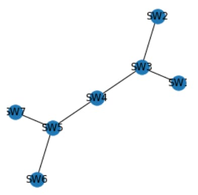
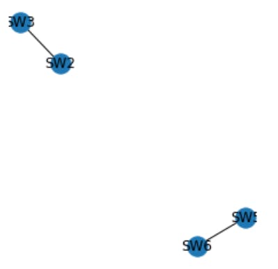
With our Graph ready, let's make some analysis and plots (for plotting I recommend using Jupyterhub), in the first analysis, we separate from the main graph all the devices that have the VLAN 10 in the VLAN database, to do that create a list with all nodes that have the VLAN 10 then use the subgraph method.
vlan10Nodes = []
for node in G.nodes:
    if '10' in G.nodes[node]['vlans']:
        vlan10Nodes.append(node)
vlan10Graph = nx.subgraph(G , vlan10Nodes)
With our graphs ready let’s plot then using matplotlib
import matplotlib.pyplot as plt
plt.figure(figsize=(3, 3))
nx.draw(G, with_labels=True)

plt.figure(figsize=(3, 3))
nx.draw(vlan10Graph, with_labels=True)
 Looking at both diagrams it’s evident that the VLAN 10 is not continuously connected, is divided into two segments, which can be a configuration error or VLAN reuse and, in both cases, some action can be done to improve the infrastructure by fixing the configuration or changing the VLAN ID of one of the segments.
But that analysis was a visual one, and so an undesired one, to do that in a programmatic way use the connected_components module of NetworkX that returns a generator of connected objects, and with that generator is just calculates the length of his list.
len(list(nx.connected_components(vlan10Graph)))
If that length is greater than 1, you have a divided VLAN, what might indicate that your environment has a configuration error, to solve it you need to find what device has a missing configuration and, for that, NetworkX provides a method that calculates all the paths between two nodes.
In our scenario, the devices SW2 and SW6 are in access level so let’s calculate all the paths between them and check if all nodes are present in vlan10Graph, those that are missing should be incorrected configured.
for path in nx.all_simple_paths(G, source='SW6', target='SW2'):
    for node in path:
        if( not vlan10Graph.has_node(node)):
            print(f"Node {node} without VLAN configuration")
Node SW4 without VLAN configuration
NetBox Integration
For the last step, we’re going to create all the devices and the connections into NetBox using his API, but before exploring the API endpoints, it’s important to have in mind some concepts of the REST architecture, the first one is what each HTTP METHOD means:
- GET: Used to retrieve (GET) some data from the API
- POST: Used to CREATE something in the API;
- PUT: Used to UPDATE something in the API;
- DELETE: Used to DELETE something in the API;
The next concept is the endpoints, which are a path of the API that represents some resource, so if you want to retrieve data from that resource you make a GET request, for CREATE a POST request, and so on.
If you want to create a device you have to make a POST request to the endpoint /dcim/devices and in the documentation it’s required the following parameters: device_type, device_role, and site, all of those are Integers that represents the ID of the elements and, of course, you want to give a name to that device.
So, for creating a new device on NetBox, you need to retrieve (GET) the ID’s of the device_type, device_role, and site, making a GET request to the respective endpoint with the desired parameters. Summarizing all, we have the following code:
import requests

def CreateDevice(device_name, device_type , device_role , platform , site ):
    api_token = "<your_api_token>"
    url = 'https:// <your_netbox_url>/api'
    headers = {
        'accept': 'application/json',
        'Authorization': f"Token {api_token}",
    }

    endpoint = '/dcim/platforms/'
    URI = f"{url}{endpoint}"
    platform_params = {
        'name': platform,
    }
    r = requests.get(URI, headers=headers, params=platform_params, verify=False)
    platform_response = r.json()
    platform_id = platform_response['results'][0]['id']

    endpoint = '/dcim/sites/'
    URI = f"{url}{endpoint}"
    sites_params = {
        'name': site,
    }
    r = requests.get(URI, headers=headers, params=sites_params, verify=False)
    site_response = r.json()
    site_id = site_response['results'][0]['id']

    endpoint = '/dcim/device-roles/'
    URI = f"{url}{endpoint}"
    role_params = {
        'name': device_role,
    }
    r = requests.get(URI, headers=headers, params=role_params, verify=False)
    role_response = r.json()
    role_id = role_response['results'][0]['id']

    endpoint = '/dcim/device-types/'
    URI = f"{url}{endpoint}"
    type_params = {
        'model': device_type,
    }
    r = requests.get(URI, headers=headers, params=type_params, verify=False)
    type_response = r.json()
    type_id = type_response['results'][0]['id']

    endpoint = '/dcim/devices/'
    URI = f"{url}{endpoint}"
    device_payload = {
        "name": device_name,
        "device_type": type_id,
        "device_role": role_id,
        "platform":  platform_id,
        "site": site_id
    }
    r = requests.post(URI, headers=headers, json=device_payload, verify=False)
    return r.status_code
Doing the same process to the connections, the endpoint that creates them is the “/dcim/cables/” and it requires the Interface ID that is available at the “/dcim/interfaces/” endpoint, giving the following code:
def connectDevices(localDevice , localInterface , remoteDevice, remoteInterface):
    api_token = "<your_api_token>"
    url = 'https:// <your_netbox_url>/api'
    headers = {
        'accept': 'application/json',
        'Authorization': f"Token {api_token}",
    }
    termination_type = "dcim.interface"
    endpoint = '/dcim/interfaces/'
    URI = f"{url}{endpoint}"
    localData = {
        'name': localInterface,
        'device' : localDevice
    }
    r = requests.get(URI, headers=headers, params=localData, verify=False)
    localResponse = r.json()
    localId = localResponse['results'][0]['id']
    remoteData = {
        'name': remoteInterface,
        'device' : remoteDevice
    }
    r = requests.get(URI, headers=headers, params=remoteData, verify=False)
    remoteResponse = r.json()
    remoteId = remoteResponse['results'][0]['id']
    payload = {
        "termination_a_type": termination_type,
        "termination_a_id": localId,
        "termination_b_type": termination_type,
        "termination_b_id": remoteId,
    }
    endpoint = '/dcim/cables/'
    URI = f"{url}{endpoint}"
    r = requests.post(URI, headers=headers, json=payload, verify=False)
    return r.status_code
With those modules ready we need to iterate over our graph, to add all the devices, and then to create all the connections:
for node in G.nodes:
    device_type = <A device Type>
    device_role = <A device Role>
    platform =  < A pdevice Platform>
    site = < A site >
    CreateDevice(node,  device_type , device_role , platform , site )

for edge in G.edges:
    localDevice = edge[0]
    localInterface = G.edges[edge]['data'][edge[0]]['local_interface']
    remoteDevice = G.edges[edge]['data'][edge[0]]['remote_device']
    remoteInterface = G.edges[edge]['data'][edge[0]]['remote_interface']
    connectDevices(localDevice , localInterface , remoteDevice, remoteInterface)
Conclusion
With the technics exposed in this article, you should be able to map your network environment, assuming that LLDP or CDP is enabled, and make some graph analysis.
About the Graph analysis, this article presents only a simple scenario but it can be extended for other applications, like calculating MPLS TE Tunnels or programmatically determining the best path between two nodes in your infrastructure.
Thanks for your time, I hope you enjoyed it.

